Modern 66 / 73
-
Rotnguns
- B Poster

- Posts: 23
- Joined: Tue Mar 17, 2009 8:10 pm
Re: Modern 66 / 73
Please keep posting about these technical subjects! This discussion was most informative. Thanks for sharing your knowledge with us!cedestech wrote: Wed Mar 19, 2025 1:38 pmObviously… miss typed. I will endeavor to stay off this sight for another year or so…Rotnguns wrote: Wed Mar 19, 2025 12:03 pmActually, the links do indeed carry the impulsive firing load - they transmit the load to the pins and ultimately to the frame through the large pin at the rear. That's why they have to be quite robust - they must resist crushing failure at the interface between the pins and the links in the stirrup joints; they also have to be thick enough to avoid buckling. Fortunately, they appear to be overdesigned by a fair margin. Agree that they are fun to shoot, but certainly not at high pressure levels!cedestech wrote: Wed Mar 19, 2025 6:36 am
My point is the area of the link A doesn’t touch the frame so no load is carried by it. The load is through pin B (and it’s twin on the bolt). Not shown is the frame and bolt have cut outs that “catch” the links if there is a pin failure. Also, the pin in the bolt and frame are one pin through the piece (bolt or frame) and the entire recoil pulse is being transmitted into the pin and frame by a piece of material a bit wider than 3/8”.
These rifles were not designed for high pressures/sharp recoil pulses and high round counts.
Are they cool? Yes. Are they fun to shoot? Yes. Can they be accurate? Yes. Should you hot rod them or even shoot hot modern loads out of them for thousands of rounds a year? I wouldn’t. Will they fail catastrophically ? Probably not but they will get sloppy and hopefully you’ll notice it before the fail safe design of the link to frame geometry gets demonstrated.
I just don’t want to see anyone hurt. Take my diatribe for what it’s worth.

Maybe Jason will come back and explain how silhouette will be restored to it’s former glory by the elimination of the score books…
-
Porpoise
- B Poster
- Posts: 38
- Joined: Sun Sep 11, 2016 2:21 pm
- Location: Canada
Re: Modern 66 / 73
Those illustrations are both wrong. The top one shows that the frame does take the stress at the rear while appearing to show only the pin at the middle and I don't recognize that picture at all where the link contacts the bolt. The second illustration omits where the link rotates in the frame at the back but then shows the links bearing on each other in the middle unlike the first illustration which just shows the pin taking the load. I am going to take a pic of a real gun
-
Porpoise
- B Poster
- Posts: 38
- Joined: Sun Sep 11, 2016 2:21 pm
- Location: Canada
Re: Modern 66 / 73
You do not have the required permissions to view the files attached to this post.
-
Porpoise
- B Poster
- Posts: 38
- Joined: Sun Sep 11, 2016 2:21 pm
- Location: Canada
Re: Modern 66 / 73
You do not have the required permissions to view the files attached to this post.
-
Porpoise
- B Poster
- Posts: 38
- Joined: Sun Sep 11, 2016 2:21 pm
- Location: Canada
Re: Modern 66 / 73
Ok, only the third one is actually wrong where it doesnt show the link pivoting in the frame at the rear but the others are easy to misinterpret
-
Rotnguns
- B Poster
- Posts: 23
- Joined: Tue Mar 17, 2009 8:10 pm
Re: Modern 66 / 73
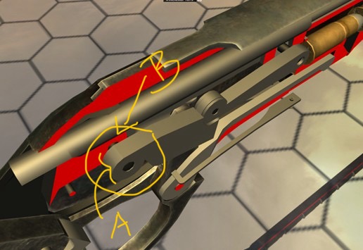
Which one is the third illustration? Referring to the illustration that I copied from a World of Guns animation, cedestech marked the rear pin and one of the parallel rear links with yellow: A and B. I think it clearly shows that the rear link pivots on the large rear pin, which creates a stirrup joint. The links, connected by pin joints, are called "two-force members." The line of action of the force they transmit runs through the joints on the ends of the links. The rear links transmit the force to the frame through the rear pins. The force from the pin bearing on the frame causes bearing stress on the contact surface between the pin and the frame.Porpoise wrote: Mon Mar 24, 2025 7:00 pm Ok, only the third one is actually wrong where it doesnt show the link pivoting in the frame at the rear but the others are easy to misinterpret
-
Porpoise
- B Poster
- Posts: 38
- Joined: Sun Sep 11, 2016 2:21 pm
- Location: Canada
Re: Modern 66 / 73
I think it is obvious from my photos that the links are made to bear at the bolt and frame and each other in the middle. Even if the setup were machined so there was more clearance around the links than between the pins and their holes, so that the pins would take the thrust , you can see that any wear on the pins would create a situation where the links would start bearing. The middle pin must take some stress, but only so much as to keep the links in line under thrust
-
Rotnguns
- B Poster
- Posts: 23
- Joined: Tue Mar 17, 2009 8:10 pm
Re: Modern 66 / 73
Interestingly, the middle pin is actually two pins - one for each of the parallel linkages. Cannot tell by looking straight down at the linkage - need an oblique view, like the one that I posted. However, the two middle pins still form stirrup joints and are thus still each in double shear, so they can be smaller, since they each take only the load transmitted by one link. The pins and links are very robust; I don't agree that they would yield as you suggest, not discounted your opinion, though. The cutouts in the linkage are primarily to afford a slimmer profile (in contrast with a Marlin, which uses a different linkage that needs to be wider). You can see the pin capacities for smaller pins from the McMaster catalog page I posted in an earlier comment. This design is a very common application of a well-known mechanical linkage.Porpoise wrote: Tue Mar 25, 2025 3:44 pm I think it is obvious from my photos that the links are made to bear at the bolt and frame and each other in the middle. Even if the setup were machined so there was more clearance around the links than between the pins and their holes, so that the pins would take the thrust , you can see that any wear on the pins would create a situation where the links would start bearing. The middle pin must take some stress, but only so much as to keep the links in line under thrust
-
Porpoise
- B Poster
- Posts: 38
- Joined: Sun Sep 11, 2016 2:21 pm
- Location: Canada
Re: Modern 66 / 73
The McMaster catalogue in this context is meaningless along with everything else in your postRotnguns wrote: Tue Mar 25, 2025 7:08 pmInterestingly, the middle pin is actually two pins - one for each of the parallel linkages. Cannot tell by looking straight down at the linkage - need an oblique view, like the one that I posted. However, the two middle pins still form stirrup joints and are thus still each in double shear, so they can be smaller, since they each take only the load transmitted by one link. The pins and links are very robust; I don't agree that they would yield as you suggest, not discounted your opinion, though. The cutouts in the linkage are primarily to afford a slimmer profile (in contrast with a Marlin, which uses a different linkage that needs to be wider). You can see the pin capacities for smaller pins from the McMaster catalog page I posted in an earlier comment. This design is a very common application of a well-known mechanical linkage.Porpoise wrote: Tue Mar 25, 2025 3:44 pm I think it is obvious from my photos that the links are made to bear at the bolt and frame and each other in the middle. Even if the setup were machined so there was more clearance around the links than between the pins and their holes, so that the pins would take the thrust , you can see that any wear on the pins would create a situation where the links would start bearing. The middle pin must take some stress, but only so much as to keep the links in line under thrust
-
edgehit
- AAA Poster

- Posts: 663
- Joined: Thu Apr 13, 2006 3:24 pm
Re: Modern 66 / 73
You guys crack me up. These modern reproductions have been finite-element modeled for stresses exerted by multitudes of chamber pressures exceeding SAAMI or CIP spec loads.
- Joe